Fluxon Motor
A Custom Gear Motor is an engineered drive unit built for a specific machine, not a standard motor with a different label. It combines an electric motor, gear train, housing, bearings, seals, and control requirements. Each part must match the application.
Dr. Martin Doppelbauer, an electric-drive specialist, states, “Efficiency begins with the complete drive system, not the motor alone.” This principle explains why customization matters. A conveyor may need high starting torque and slow, steady rotation. A medical actuator may require quiet operation, compact dimensions, and precise positioning. A packaging machine may demand repeated starts without excessive heat.
Inside the unit, electrical energy creates rotational force in the motor. The gearbox then changes speed and torque through interacting gears. A reduction ratio of 20:1 can greatly increase output torque while lowering shaft speed. The final result depends on gear geometry, lubrication, load direction, duty cycle, and heat removal.
The design process is rarely perfect on the first attempt. Engineers may discover that a motor fits physically but overheats during continuous operation. A smaller gearbox may reduce cost but shorten service life. These trade-offs deserve careful testing.
This guide explains what a Custom Gear Motor is, how its internal stages work, and why specifications matter. It also examines torque, speed, efficiency, noise, maintenance, and application fit. Real-world performance can differ from catalog figures. That detail is easy to overlook. Reliable selection therefore requires measured loads, operating conditions, and verification from qualified manufacturers.
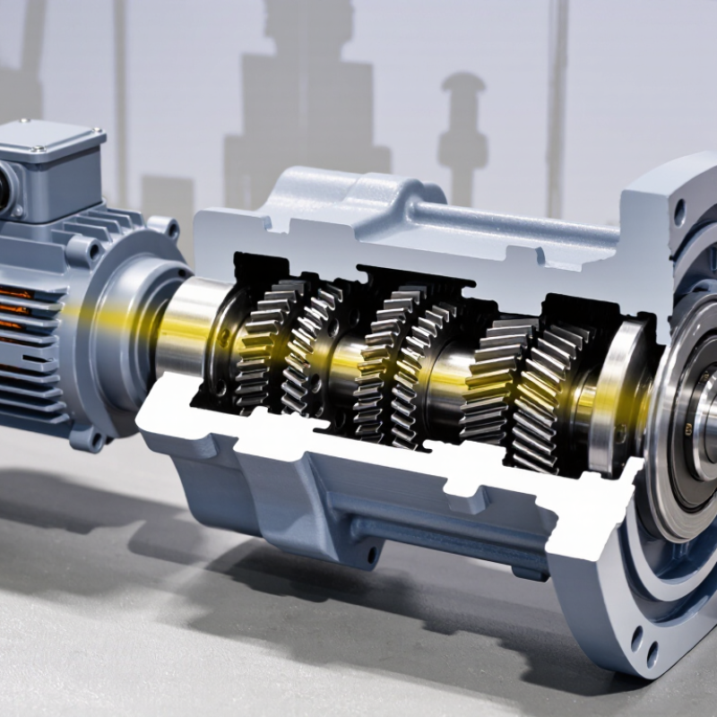
A custom gear motor combines an electric motor with a matched gearbox for a specific machine task. Its core purpose is simple: deliver controlled motion with the required torque, speed, and mounting arrangement. Unlike a standard unit, it can be designed around a measured load, operating cycle, voltage, noise limit, or restricted installation space.
Inside the assembly, the motor creates rotation. The gear stages then reduce speed and increase usable torque. The final output turns a conveyor, valve, actuator, or positioning mechanism. Engineers normally review starting torque, continuous load, duty cycle, heat, and shaft alignment before selecting the gear ratio. In practical testing, small alignment errors can create vibration and shorten service life. That detail is easy to underestimate.
Tips: Measure the real load, not only the rated load. Check stall conditions and repeated starts. Leave room for cooling and maintenance. A quieter gear train may improve the machine, but it can increase cost or reduce compactness. There is rarely a perfect choice. I have found that early testing reveals assumptions that calculations can miss. Even a carefully specified motor may need revision after observing noise, temperature, or backlash in the finished equipment.
| Data Dimension | Definition or Specification | How It Works or Why It Matters | Typical Customization Considerations |
|---|---|---|---|
| Basic Definition | A custom gear motor is an integrated motor-and-gearbox assembly designed or configured for the requirements of a specific application. | The motor produces rotational power, while the gearbox changes speed and torque before the output reaches the driven mechanism. | The motor type, gearbox architecture, dimensions, output interface, control method, and environmental protection can be selected for the application. |
| Core Purpose | To deliver controlled rotary motion with the required output speed, torque, direction, and operating reliability. | Gear reduction generally lowers output speed and increases available output torque, subject to efficiency and load limitations. | The design balances torque, speed, physical size, noise, efficiency, service life, and cost. |
| Main Power-Conversion Path | Electrical input → motor electromagnetic force → motor shaft rotation → gear reduction → mechanical output. | Electrical energy creates a rotating magnetic field and shaft motion; meshing gears transmit and modify that motion. | The input voltage, current, duty cycle, gear ratio, and output load must be matched to prevent overheating or premature wear. |
| Motor Options | Common choices include brushed DC, brushless DC, AC induction, and stepper motors. | Each motor type has different characteristics for speed control, starting torque, maintenance, positioning, efficiency, and control complexity. | Selection depends on the available power supply, required motion profile, control system, operating environment, and maintenance requirements. |
| Gearbox Types | Typical architectures include spur, helical, planetary, worm, bevel, and parallel-shaft gearboxes. | Gear geometry determines how power is transmitted and affects efficiency, noise, load capacity, compactness, and self-locking behavior. | The gearbox is chosen according to torque, ratio, allowable backlash, shaft arrangement, space limits, and expected service life. |
| Gear Ratio | The gear ratio is the relationship between the input speed and the output speed of the gearbox. | For a reduction gearbox, a higher ratio normally produces a lower output speed and a higher theoretical torque multiplication. | The ratio is selected from the required output speed, motor speed, acceleration, load inertia, and available torque margin. |
| Output Torque | Output torque is the rotational force available at the gearbox output shaft, usually expressed in N·m or mN·m. | A simplified relationship is: output torque ≈ motor torque × gear ratio × gearbox efficiency. | Continuous torque, peak torque, starting torque, shock loads, and allowable duty cycle should all be evaluated separately. |
| Output Speed | Output speed is the rotational speed delivered by the gearbox, commonly measured in revolutions per minute (rpm). | The gearbox reduces or modifies the motor’s native speed to match the motion required by the machine. | The required speed range, speed stability, acceleration time, and control resolution influence the final configuration. |
| Efficiency | Efficiency is the ratio of mechanical power delivered at the output to the power supplied to the motor and drive system. | Friction, gear tooth sliding, bearing losses, seals, lubrication, and electrical resistance reduce the power available at the output. | High-efficiency designs are important for battery operation, continuous duty, thermal management, and energy-sensitive equipment. |
| Mechanical Interface | The mechanical interface includes the mounting pattern, shaft geometry, keyway, flange, housing, and allowable installation orientation. | A compatible interface allows the gear motor to transfer torque safely and fit within the host machine. | Custom dimensions, hollow or solid output shafts, mounting holes, connectors, and cable exits can be adapted to the equipment. |
| Control and Feedback | Control may be open-loop or closed-loop, with optional feedback from encoders, Hall sensors, or other position and speed sensors. | Feedback enables the controller to monitor motion and correct speed, position, or torque deviations. | The required accuracy, repeatability, response time, communication interface, and controller compatibility determine the feedback configuration. |
| Environmental Requirements | Environmental factors include temperature, dust, moisture, chemicals, vibration, shock, and installation altitude. | These conditions affect insulation, lubrication, sealing, corrosion resistance, cooling, and bearing life. | Housing materials, sealing level, surface treatment, lubricant, thermal protection, and connector selection may be customized. |
| Common Applications | Custom gear motors are used in conveyors, robotics, automated equipment, medical devices, actuators, pumps, valves, and positioning mechanisms. | They provide compact, controllable rotary motion where a standard motor alone cannot meet the required speed or torque conditions. | The application determines the motion profile, load type, duty cycle, noise limit, operating life, and installation constraints. |
| Standard vs. Custom Design | A standard gear motor uses predefined specifications, while a custom gear motor is modified or engineered to satisfy application-specific requirements. | Customization can improve fit, performance, integration, and reliability when off-the-shelf products do not provide a suitable match. | Typical custom elements include the gear ratio, shaft, mounting arrangement, motor winding, sensors, connector, housing, brake, and control features. |
It combines an electric motor with a matched gearbox. It delivers controlled speed, torque, and mounting flexibility. The design fits a specific machine task.
The motor creates rotation and torque. The gearbox reduces speed and increases usable torque. Some power becomes heat, friction, and vibration. Efficiency is never perfect.
Real loads may differ from rated loads. Startup torque and repeated starts can create extra stress. Measure peak loads, not only normal operating loads. This assumption is easy to miss.
Engineers balance required output speed and torque. A conveyor may need steady rotation at 60 revolutions per minute. Another machine may need short bursts and precise movement. The correct ratio depends on actual operation.
Provide load weight, startup torque, speed, and duty cycle. Include voltage, mounting space, shaft requirements, and operating temperature. Dust, moisture, and frequent cleaning also affect the design. Details matter here.
It can improve motion control, torque delivery, and installation fit. A quieter gear train may reduce machine noise. However, it may increase cost or reduce compactness. There is no perfect choice.
Calculations may miss vibration, noise, heat, or backlash. Testing can reveal unexpected startup loads. Measure current, temperature, output speed, and shaft movement. Test the real position.
Small alignment errors may create vibration. They can increase noise and shorten service life. Inspect shaft alignment during installation and testing. Do not underestimate it.
Leave room for cooling, inspection, and servicing. Choose materials and seals for the working environment. Review temperature, noise, and backlash after installation. Initial specifications may need revision.
A Custom Gear Motor is an integrated drive system designed to deliver the specific speed, torque, and motion required by a particular machine or application. It combines an electric motor with a gearbox, which may include gears, shafts, bearings, seals, housing, and control interfaces. Working together, these components reduce motor speed and increase torque while transferring power efficiently and consistently to the driven equipment.
The customization process begins by evaluating load requirements, operating speed, duty cycle, installation space, environmental conditions, and control needs. Engineers can then select suitable gear ratios, motor ratings, mounting arrangements, materials, and protection features. Custom Gear Motor solutions are commonly used in conveyors, automation equipment, medical devices, packaging systems, robotics, and other machinery. Their main benefits include improved performance, compact design, reliable operation, and easier system integration. When selecting one, users should consider torque demand, efficiency, noise, durability, maintenance requirements, energy consumption, and compatibility with the complete application.